
Alankar Kotwal, Anat Levin and Ioannis Gkioulekas
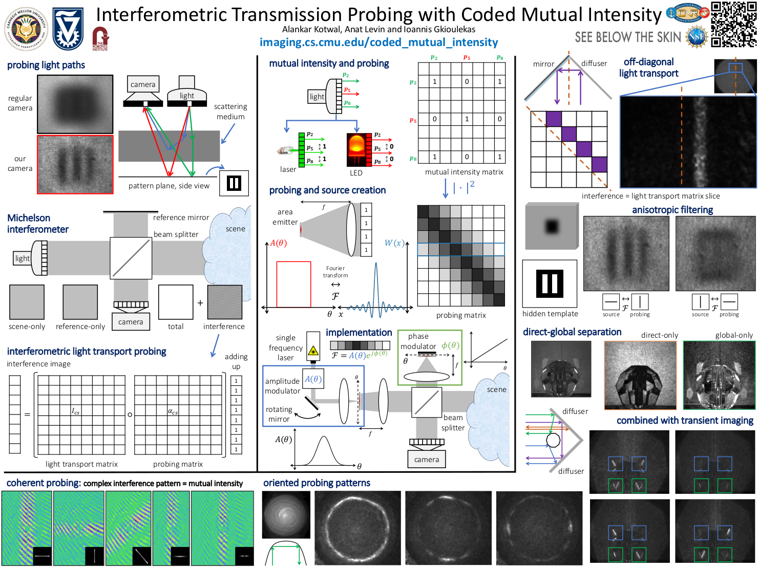
We introduce a new interferometric imaging methodology that we term interferometry with coded mutual intensity, which allows selectively imaging photon paths based on attributes such as their length and endpoints. At the core of our methodology is a new technical result that shows that manipulating the mutual intensity properties of the light source used in an interferometric system is equivalent, through a Fourier transform, to implementing light path probing patterns. These patterns can be applied to either the coherent transmission matrix or the incoherent light transport matrix describing the propagation of light in a scene. We test our theory by building a prototype inspired from the Michelson interferometer, extended to allow for programmable phase and amplitude modulation of the illumination in the interferometer. We use our prototype to perform experiments such as visualizing complex fields, capturing direct and global transport components, acquiring light transport matrices, and performing anisotropic descattering, both in steady-state and in combinations with optical coherence tomography.

Light propagation is an inherently multi-path phenomenon: When we look at our surroundings, we observe light that has interacted with one or multiple objects, either by reflecting on their surfaces, or by scattering in their interior. Imaging systems typically accumulate contributions from photons traveling along all of these paths irrespective of characteristics such as the paths’ origins and lengths. Computational light transport techniques attempt to measure only light that has traveled along specific subsets of all the possible paths in a scene. These subsets can be specified based on characteristics such as the endpoints and length of the paths, or combinations thereof.
Our focus is on using interferometry measure such subsets of paths. Interferometric systems operate by simultaneously measuring two light waves that originated at the same light source, and have traveled along different paths in an optical system. When superimposed on an optical sensor, the two waves will produce some measurable interference. Depending on the wave-optics properties of the original illumination, only light paths that satisfy certain characteristics will contribute to the interference. Therefore, by controlling the coherence properties of the source the waves originate from, and then measuring their interference after propagation, it is possible to isolate contributions from only specific light paths.

Our key technical result shows that performing interferometry with appropriate amplitude modulation of the source and phase modulation of the reference arm is equivalent to probing the scene’s transmission matrix with the corresponding coded mutual intensity matrix. This coded mutual intensity matrix is a Toeplitz matrix generated by the Fourier transform of the modulation. We thus refer to our imaging method as interferometry with coded mutual intensity.
To achieve a specified Toeplitz probing matrix, we compute the inverse Fourier transform of the probing kernel generating the matrix and use its amplitude and phase to program the amplitude and phase modulation components of our system. Next, to capture probing measurements of a scene, we first capture images at multiple sub-wavelength phase shifts, implemented using phase modulation. We then process these measurements to estimate the phase and amplitude of the interference component.

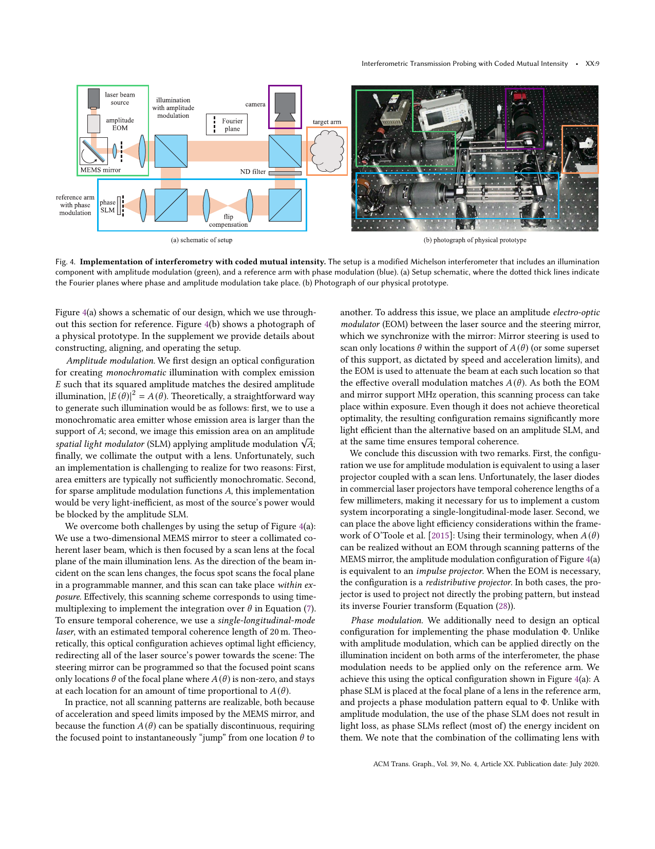
We built a modified Michelson interferometer that includes an illumination component with amplitude modulation (green), and a reference arm with phase modulation (blue). In the setup schematic on the left, the dotted thick lines indicate the Fourier planes where phase and amplitude modulation take place. On the right is a photograph of our physical prototype.
Our results emphasize probing types that are impossible using previous interferometric techniques by Gkioulekas et al., or light-inefficient using projector-camera techniques by O'Toole et al.

These images show the real part of transmission matrices probed using the amplitude modulation functions A shown in the inset. (a) Probing with horizontal line amplitude modulation functions of different widths. As we increase the size of A, the extent of its probing kernel decreases. (b) Probing with line amplitude modulation functions of different orientations. As we rotate A, the probing kernel rotates as well. (c) Probing with horizontal line amplitude modulation functions of different profiles. The absolute values of the profiles of A and the probing kernel are shown in (d) and (e), respectively.

(a) Pattern consisting of two vertical stripes behind a thick semi-transparent scatterer. (b) In a regular image, the stripe cannot be resolved because of scattering. (c) Probing the scene with a horizontal Laplacian-of-Gaussian kernel that matches the orientation of the stripes enhances their contrast and makes them clearly visible. (d) Probing the scene with a vertical kernel results in the two stripes remaining obscured.

Left to right: regular photograph of the scene, direct-only and global-only images captured using our incoherent probing technique. The cup and gummy bear appear metallic in the direct-only images, as the subsurface scattering effects dominating their appearance are only measured in the global-only images. The direct-only image of the bead is missing the strong specular reflections on the bead’s faces and the on the wall, which are prominent in the global-only image.

Left to right: regular image, and isolated frames of the transient sequence at the same time instance when using no probing, anisotropic probing at +45°, and anisotropic probing at −45°. In the cup scene, when using probing, only the parts of the caustic that match the probing kernel are maintained, and the rest of the caustic is suppresed. Likewise, in the bead scene, different reflections on wall and on the bead faces are maintained and suppressed, depending on the probing kernel used. Below are the relevant sections of transients from these scenes.
Cup scene, transient with no probing
Cup scene, transient with direct-only probing
Cup scene, transient with anisotropic horizontal probing
Cup scene, transient with anisotropic vertical probing
Cup scene, transient with anisotropic probing at -45°
Cup scene, transient with anisotropic probing at +45°
Cup scene, transient with wide horizontal kernel
Cup scene, transient with narrow horizontal kernel
Bead scene, transient with no probing
Bead scene, transient with anisotropic probing at -45°
Bead scene, transient with anisotropic probing at +45°
Bead scene, transient with direct-only probing
Since the source and probing kernel are related by a Fourier transform, the source for anisotropic probing is a flipped version of the direction of probing. Similarly, the source required for wide probing is a narrow one and vice versa. The next figures illustrates this.

(a) Photograph of the scene for visualization. (b) Light paths in the scene: blue are direct paths, purple and yellow are two-bounce reflection paths, and green are retroreflecting paths. Below the schematic is a regular image captured from this scene. (c) The two-dimensional light transport matrix for this scene: direct and retroreflecting paths show up on the diagonal, and the two-bounce reflection paths show up on the antidiagonal. (d) Measured light transport matrix, with regions corresponding to different matrix parts in (c) marked in color. (e) Representative probing kernels used to measure the light transport matrix. (f) Measurements using the probing kernels in (e), where the top and bottom images are due to two-bounce reflection paths, and the middle image is due to direct and retroreflecting paths. The dashed line in (b) and (f) indicates the location of the corner. An illustration of the acquisition process is shown below:
All code and data for generating the figures in the paper is available in this Box folder. Please note that some of the data is still uploading...
For an in-depth description of the technology behind this work, please refer to our SIGGRAPH 2020 paper, supplement, poster, slides, and video recording.
Alankar Kotwal, Anat Levin and Ioannis Gkioulekas. "Interferometric Transmission Probing with Coded Mutual Intensity", SIGGRAPH 2020
This work was supported by NSF Expeditions award 1730147, DARPA REVEAL contract HR0011-16-C-0028, ONR DURIP award N00014-16-1-2906, ERC 635537, ISF 1046-14, and the Ollendorff Minerva Center of the Technion.